Uni-wale?
-
Glen Smith

- Posts: 3719
- Joined: Sat May 08, 2004 9:08 am
- Location: Baie-St-Paul, Quebec, Canada
-
Redbird Bernie

- Posts: 28
- Joined: Sun Oct 17, 2010 3:14 pm
- Location: Illinois, USA
These are all very interesting posts, but what we really need on our canoes are port-o-potties and full size refrigerators.:eyebrows Anybody working on that?
It seems like that Power Rocker seat only comes down a few degrees. How is that sufficient to accommodate kneeling?
Sparks is a really nice craft. While it must have been expensive to build, I am sure that it is a drop in the bucket compared to the cost of the extension cord. Next step, electrify the water?:twisted evil
It seems like that Power Rocker seat only comes down a few degrees. How is that sufficient to accommodate kneeling?
Sparks is a really nice craft. While it must have been expensive to build, I am sure that it is a drop in the bucket compared to the cost of the extension cord.

Well... the website with the photos of the removeable yoke I referred to earlier is gone and the builder isn't answering an email I sent several day's ago.
This was a very straightforward design and shouldn't be difficult to design on one's own... simple and quick, slides in under the inwale, and fastened with bungees.
This was a very straightforward design and shouldn't be difficult to design on one's own... simple and quick, slides in under the inwale, and fastened with bungees.
-
Bryan Hansel

- Posts: 678
- Joined: Fri May 14, 2004 6:36 pm
- Location: Grand Marais, MN
- Contact:
It should be pretty close to balanced with it a little stern heavy on my Bell Magic. I'll have to work out the final distance once I build it. The balance can be adjusted by extending the front prongs forward. I always add Chosen Valley Yoke Pads to my yokes, so I don't see seat interference as an issue.Redbird Bernie wrote:Bryan, while your prototype drawing based on the photo from Moonman looks fine, I have some difficulty visualizing whether or not this design will work well from a balance point of view, plus the seat may end up uncomfortably close to your back and neck during portaging.
What if the seat consisted of two parts, a yoke shaped back rail and the seat portion. I am thinking of a curved seat that mounts onto or inserts into the curved portion of the yoke. The yoke would be permanently attached to the hull.
Has anyone considered alternative methods of portaging. Would it make sense for example to carry the canoe on its side in similar fashion to a suitcase? Think both above or below the carrier's belt line. Could the canoe be portaged with the hull down and strapped on top of an especially designed backpack?
Bernie
I've tried to carry my solo canoe in other ways, but overhead is the easiest. Sometimes, the portage trail isn't wide enough to carry it on the side. Although, on one shoulder, like a kayak works in some places. I've seen a portage backpack with a metal frame and a rest for the canoe's yoke. I tried it and didn't like it. You had to use ropes at each end to keep the canoe balanced on the backpack.
-
Patricks Dad

- Posts: 1476
- Joined: Wed Oct 13, 2004 1:11 pm
- Location: Warrenville, Illinois
-
Glen Smith
- Posts: 3719
- Joined: Sat May 08, 2004 9:08 am
- Location: Baie-St-Paul, Quebec, Canada
-
Patricks Dad
- Posts: 1476
- Joined: Wed Oct 13, 2004 1:11 pm
- Location: Warrenville, Illinois
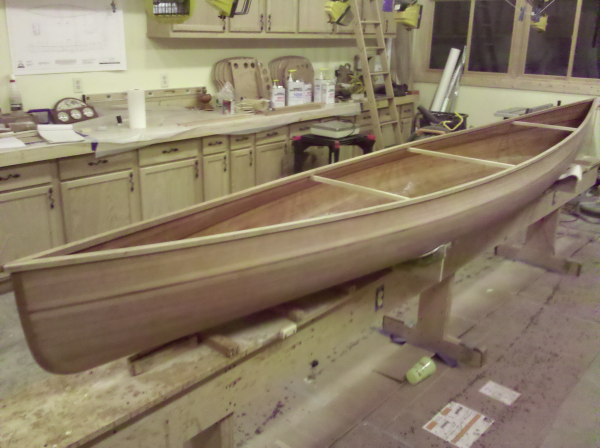
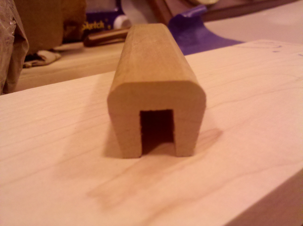
These uniwales are made of cherry. The original stock was 7/8" wide by 3/4 tall. The channel is 1/2" deep and a bit under 5/16" wide. They weighed 1.86 pounds each (before tapering the inside but that tapering won't remove too much weight). Both of them installed added 4 pounds to the total weight of the canoe (~5 oz of thickened epoxy).
They were easy to install. They followed the curve of the hull nicely in both dimensions. Once on, they pretty much stayed there all by themselves. We put a bit of weight on top of them in a few places to hold them down. We did use a couple clamps on the ends to ensure a tight joint between the two sides and to the top of the stems.
Because they had an inherent "interest" in relaxing, there was virtually no gap between the uniwale and the outside of the hull amidship. At the ends, they tended to want to move any slack to the outside. We inserted toothpicks between the uniwale and the inside of the hull to ensure a tight fit on the outside. Once I'm all done, I'll go back and put a small bead of epoxy on the inside to ensure a tight seal there. Overall, it was a pretty easy task.
I'm satisified with the look. I'd do it again.
I'd probably cut the channel a bit deeper (I was originally planning on a 3/16" thick top but cut it a bit thicker worried that it might split - probably unwarranted worry). I cut the channel with just a table saw. It allowed me to cut it exactly the width I wanted (I didn't have a router bit the right size). To get the size, I experimented a bit with a couple scraps of the uniwale material. I cut a channel that appeared to be in the right neighborhood and then slid it up and down the sheerline to find points where it was too tight. Those tight spots I sanded as much as I thought reasonable and then cut a narrower channel scrap and did it again until I was satisfied that the thickness of the sheer line was relatively consistent and that the channel thickness was appropriately snug. Then I cut the channel on the real uniwale and did a dry fit. It took a couple cracks at it to get the exact angle between the 2 uniwales to make the joints between them at the bow and stern look good.
Before installing the uniwales, I drew a pencil mark along the outside of the hull just under 1/2" below the sheer line. When the uniwale was properly installed, the pencil mark will be covered/invisible. This helped us ensure that the joint was fully seated (and all necessary epoxy squeeze-out was done).
-
Bryan Hansel
- Posts: 678
- Joined: Fri May 14, 2004 6:36 pm
- Location: Grand Marais, MN
- Contact:
-
BearLeeAlive
- Posts: 196
- Joined: Tue Aug 18, 2009 7:00 pm
-
Patricks Dad
- Posts: 1476
- Joined: Wed Oct 13, 2004 1:11 pm
- Location: Warrenville, Illinois
My thoughts on attaching thwarts:
1. Don't taper the inside of the uni-wale where the thwart will attach. Then Either:
A. Use biscuits between the end of the thwart and the inwale to ensure a firm permanent epoxy bond between the thwart and the inwale. or:
B. Add another 1/2" of inwale stock 5-6" long (tapered to zero width on each end) to make the inwale a more "traditional" width where the thwart will attach and bolt the thwart to inwale as usual.
I'm thinking of using "A" for thwarts and "B" for seat mounting (but haven't decided on the seat approach just yet).
-
Patricks Dad
- Posts: 1476
- Joined: Wed Oct 13, 2004 1:11 pm
- Location: Warrenville, Illinois
Moonman,
yes, you could just epoxy the thwart ends to the hull side and the underside of the uniwale. That would increase the gluing surface area above just glueing the butt ends to the inwale. I would think that a joint between the end of the thwart and the inwale might look cleaner however. And with a biscuit installed between them, would pretty much match the gluing surface area and maximize shear strength. I didn't taper the inside of my uniwales yet to allow me to put off this decision until later. I'm currently leaning toward the "biscuit with the top surface of inwale and thwart flush" approach but will look at a couple alternatives.
I'd be very interested in experiences other builders may have had with these various approaches....
For seats, I'm now leaning toward not using cleats. I need to look at it further, but I recall that the seat height recommendation would suggest that the cleats would fall on or near the shoulder chine. This would require some wacky shapes for the cleats to conform to the shoulder chine (and may place a force on the cleat that would be incline to peel the cleat off of the hull rather than press it on albeit with a tangential component). The weight addition of widening the inwale a 1/2" and hanging the seats from the gunwale might actually be less than the weight of the cleats (although the "look" might not be as clean).
Still time to ponder....
Hi Randy,
Good point about the seat and cleat/chine issue. I was planning on using cleats when I build this boat so I will have to think again on it as well. How many inches below the shear does the chine start?
I think the biscuit and butt joint with the thwarts and inwale will be fine. Agree it will look cleaner as well. The the thwarts only have to hold the hull together and with the chine returning the hull inwards I don't think it will be an issue at all. Might be a different issue with a yoke though (unless you thickened the inwale as you mentioned), but if still planning on the yoke integrated to the seat, then not an issue - although there may be some additional considerations now that the seat is hanging, in that the downwards force and bouncing of an integral seat/yoke will be directly applied to the seat hangers....
Moonman.